

FLANGE FACE TYPES
2020-04-23
The ASME B16.5 and ASME B16.47 norms mention a few different types of flange faces:
- Flat face flange (FF)
- Raised face flange (RF)
- Ring joint flange (RTJ)
- Lap joint flange
- Male and female flange (M&F)
- Large and small tongue-and-groove flange (T&G)
")
Let’s take a closer look at the different types of flange faces, RF, FF, lap joint, ring joint, grooved:
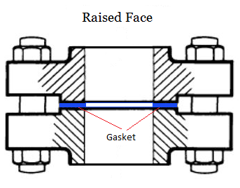
RAISED FACE FLANGE (RF)
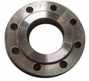
A raised face flange (RF) is easy to recognize as the gasket surface area is positioned above the bolting line of the flange.
A raised face flange is compatible with a wide range of flange gaskets, ranging from flat to semi-metallic and metallic types (as, for example, jacketed gaskets and spiral wound gaskets), either ring or full face.
The main scope of a raised face flange design is to concentrate the pressure of the two mating flanges on a small surface and increase the strength of the seal.
The height of the raised face depends on the flange pressure rating as defined by the ASME B16.5 specification (for pressure classes 150 and 300, the height is 1.6 mm or 1/16 inch, for classes from 400 to 2500, the raised face height is approximately 6.4 mm, or 1/4 inch).
The most common flange finish for ASME B16.5 RF flanges is 125 to 250 micron Ra (3 to 6 micron Ra). The raised face is, according to ASME B16.5, the default flange face finish for manufacturers (this means that buyer shall specify in the order if another flange face is required, as flat face or ring joint).
Raised face flanges are the most sold type of flange, at least for petrochemical applications.
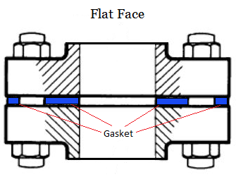
FLAT FACE FLANGE (FF)
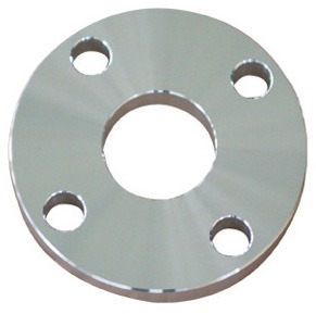
Flat face flanges (FF) have a contact surface having the same height as the bolting line of the flange. Full face gaskets, generally of the soft type, are used between two flat face flanges.
According to ASME B31.3, a flat face flange should never be mated with a raised face flange as the resulting flanged joint would definitely leak.
RING JOINT FLANGE (RTJ)
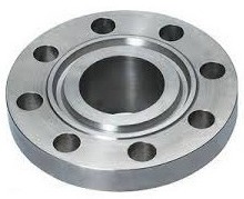
A ring joint flanges (RTJ) is used when a metal-to-metal seal between the mating flanges is required (which is a condition for high-pressure and high-temperature applications, i.e. above 700/800 C°).
A ring joint flange features a circular groove to accommodate a ring joint gasket (oval, or rectangular).
As the two ring joint flanges are bolted together and then tightened, the applied bolting force deforms the gaskets inside the flange groove creating a very tight metal-to-metal seal. To make this happen, the material of the ring joint gasket has to be softer (more ductile) than the material of the flange.
RTJ flanges can be sealed by RTJ gaskets of different styles (R, RX, BX) and profiles (example: octagonal/oval for the R style).
The most common RTJ gasket is the R style with an octagonal section, as it ensures a very strong seal (the oval section is an older type). A “flat groove” design, however, accepts both RTJ gaskets having an octagonal or oval section.

LAP JOINT FLANGE
A lap joint flange has a flat face, which is not used to seal the flanged joint but simply hosts the back of a stub end. The sealing surface is actually on the stub end itself and may be either flat face or raised face.

TONGUE AND GROOVE FLANGE (T AND G)
Two tongue and groove flanges (T&G face) perfectly fit one into the other: one flange has a raised ring, the other a groove and they can be mated easily (the tongue enters the groove and seals the joint).
Tongue and groove flanges are standardized in both large and small types.
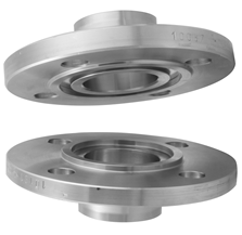
MALE AND FEMALE FLANGE (M AND F)
Similarly to tongue and groove flanges, male and female flanges (M&F face type) match one to the other as well.
One flange has an area extended beyond its face area, the male flange, the other flange has a matching depression machined on the facing surface, the female flange.
The female face is 3/16” deep, while the male face is 1/4″ high, and both of them are smooth finished.
The outer diameter of the female face retains the gasket.
FLANGE FACE FINISH
To ensure that a flange mates with the gasket and the companion flange perfectly, some roughness is required on the flange surface area (RF and FF flange finish only). The type of roughness on the flange face surface defines the type of “flange face finish”.
Common types are stock, concentric serrated, spiral serrated and smooth flange finish.
Steel flanges are available with four basic face finish, however, the common objective of any type of flange face finish is to create the desired roughness on the face of a flange to ensure a strong match between the flange, the gasket, and the mating flange and thus provide a high-quality seal.

Source: Officine Orsi, Italy
Let’s now dive into the most common flange face finish types:
STOCK FINISH
The stock finish is the most widespread type of finish as it suits the large majority of applications. The pressure embeds the soft face of the gasket into the flange finish and results in the formation of a good seal due to the friction existing between the contacting parts.
As the mating flanges are bolted together, gaskets get “squeezed” into the flange face surface and create a very tight seal.
A stock finish face is manufactured using a phonographic spiral groove featuring a 1.6mm radius round-nose tool with a depth of 0.15mm and a feed-rate of 0.8mm per revolution. The resulting “Ra” value (AARH) for the surface ranges from 125µinch to 500 µinch (125 µm to 12.5 µm).
SPIRAL SERRATED
Spiral serrated finish is a phonographic spiral groove type that differs from the stock finish as the groove is crafted by a 90 degrees tool (instead of a round nosed one) that creates a “V” geometry with a 45-degree serration angle.
A serrated finish, concentric or spiral, has from 30 to 55 grooves per inch and roughness between 125 to 250 µinch.
CONCENTRIC SERRATED
The concentric serrated flange finish features concentric grooves instead of spirals.
The grooves are crafted by the same 90-degree tool used for the spiral serrated finish, but the serrations have an even design on the face of the flange. To have concentric grooves, the tool has a feed rate of 0.039mm per revolution and a depth of 0.079mm.
SMOOTH FINISH OR FACE
Flanges with a smooth finish do not show visible tool markings at naked eye.
This type of flange finish is used with metal-facing gaskets such as the jacketed type.
As per the stock finish, this is achieved by having the contact surface machined with a continuous spiral groove generated by a 0.8mm radius round-nosed tool at a feed rate of 0.3mm per revolution with a depth of 0.05mm (that creates a roughness between Ra 3.2 and 6.3 micrometers, i.e. 125 – 250 microinches).
COLDWATER FINISH
The cold water finishes appear shiny to the naked eye and very smooth. The AARH value for these surfaces ranges between 85 µinch to 100 µinch. They are used with metal to metal seals (no gasket).
WHAT IS AARH?
The term AARH (“arithmetic average roughness height”) refers to the flange face smoothness/roughness. The average arithmetic roughness height values are very important during the selection of flanges and gasket materials. Higher the “Ra” values depict a more rough surface, while lower values represent the smoother surface.
Every material possesses a surface roughness and sometimes surfaces are finished deliberately to have a specific roughness (small or bigger).
The “Arithmetic Average Roughness Height” (AARH) is the common indicator to measure the roughness of a surface, and it is the average height of the irregularities on the metal surface, from the mean line as shown in the following figure.

The symbol Y1 to Y8 represent the peak heights which are measured from the mean line.
Arithmetic Average Roughness Height is usually measured in micro-inches and denoted by symbol “Ra”.
There are various standards for the roughness of surfaces, set according to their type of application. The equipment used to measure the surface roughness is the so-called “profilometer” (which are available in the contact and non-contact types).
In contact type profilometer the roughness is measured by moving the material under the profilometer stylus. However, modern equipment features non-contact measurements, leveraging the optical and ultrasonic technologies.
FLANGE AARH
ASME/ANSI defined specific roughness standards for the flanges, as the flange face finish plays a pivotal role in gasket’s reliability and service life.
According to the ASME/ANSI specifications, the serrated, spiral serrated, and concentric flange face finish should have an average roughness of 125 µinch to 250 µinch (3.2 µm to 6.3 µm).
The tool used to imprint a rough finish on the flange should have a radius of 0.06 inch (1.5mm) or larger. The groove density on the flange face should be from 45 grooves per inch to 55 grooves per inch (1.8 grooves/ mm. to 2.2 grooves/ mm.).
These are the standards for semi-metallic and nonmetallic gaskets. If the average roughness of flange face is not according to the described standards, the contacting surfaces would not properly seal and the flanged joint may wear after some time working under pressure (resulting in loss of bolt joint tightness and a possible leakage).
The soft nonmetallic materials such as PTFE may be used for more comfortable facing and better creep resistance.